|
|
|
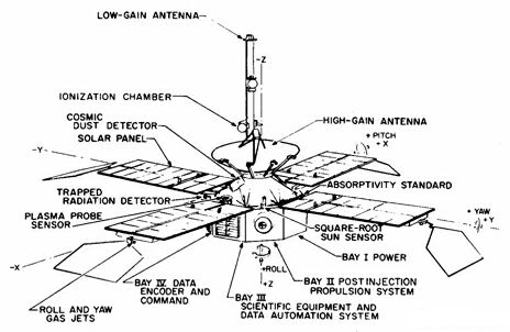
Attitude control
The spacecraft, fully stabilized in attitude, used the Sun and the star Canopus as references.
Cold-gas jets pointed the spacecraft in all three axes (pitch, yaw, and roll), and external torques
were counteracted in two of the axes by changing the positions of movable solar pressure vanes.
Gyroscopes were available for initial acquisition and for inertial control during the midcourse
maneuver.
The roll, or Z axis is a reference line paralell to the low-gain antenna mast, through the center of the spacecraft.
"Roll motion" referes to a spin about this axis. Spinning motion can be used in terms of rotation about the Z
axis, but description of "rocking" motion necessitates the use of two more coordinate axes. Spin about
the Y axis is termed "yaw" motion, about the X axis "pitch" motion.
Canopus sensor
The Canopus sensor produced, when a star was in its field of view (11° in cone and 4° in clock), error
signals proportional to the angular position displacement of the star from the spacecraft roll axis.
An electronic logic was set to respond to any object more than one-eighth as bright as Canopus.
Including Canopus, there were seven such objects visible to the Canopus sensor as the spacecraft swung
around in its search mode. A Canopus gate was used to switch the roll-axis control system to the
acquisition mode.
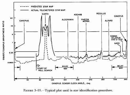
It was anticipated that star identification would be a major problem since the only information from
the Canopus sensor, other than the error signal, was a brightness measurement and the cone angle of an
object within ± 5°. Therefore, a map-matching technique was developed to identify objects seen during
the roll search mode. Fundamental to the plan was an a priori telemetry-type map of the expected sensor
brightness output as a function of clock angle. A mathematical model of the Canopus sensor and the sky,
including the Milky Way, was developed so that, with available trajectory information, an IBM 7094
computer could be programmed to print, before launch, a map of the expected telemetry output of the
brightness channel during roll search. This then could be matched with an actual telemetry map to
identify observed objects. Initially the actual telemetry map produced by a complex computer program
after receipt of the telemetry was statistically correlated with the a priori map and other data
available from the spacecraft. Whenever an object was acquired after a roll search, the probability
that each acquirable object had been acquired was calculated. If the object were not Canopus, another
roll search was instituted and another computer run made until Canopus could be identified as the object
acquired. This procedure was necessary because of the lack of knowledge concerning the absolute
calibration of the Canopus sensor for all stars and the integrated background of stars in the field
seen by the sensor.
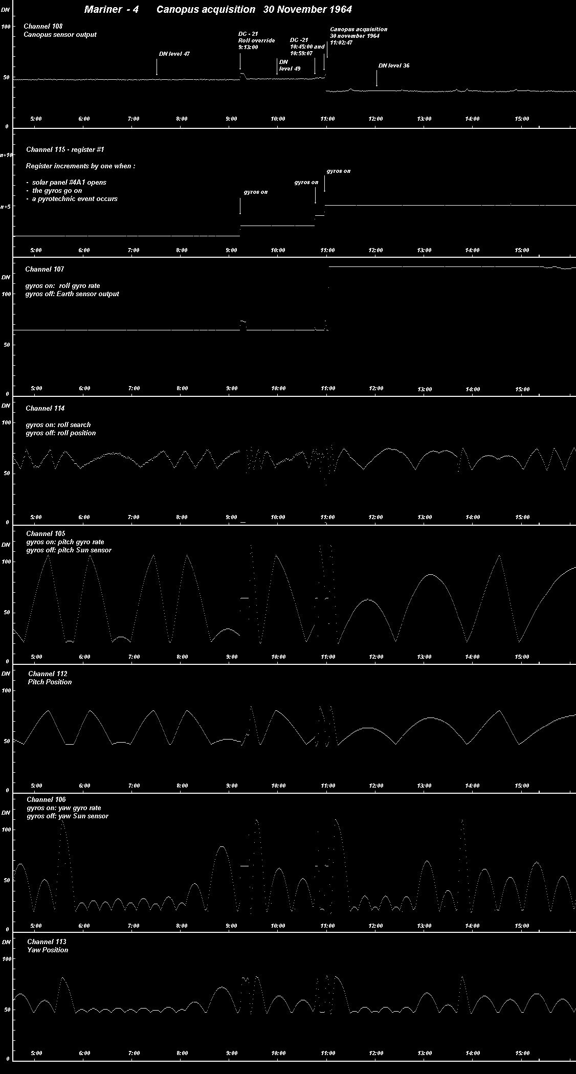
Command: DC-21
Function : Roll override, negative increment
Effect : Simulates Canopus acquisition logic violation. Turns on gyros. Applies negative roll search
signal to roll gas jet electronics. Causes spacecraft to begin counterclockwise roll search to acquire
a new target.
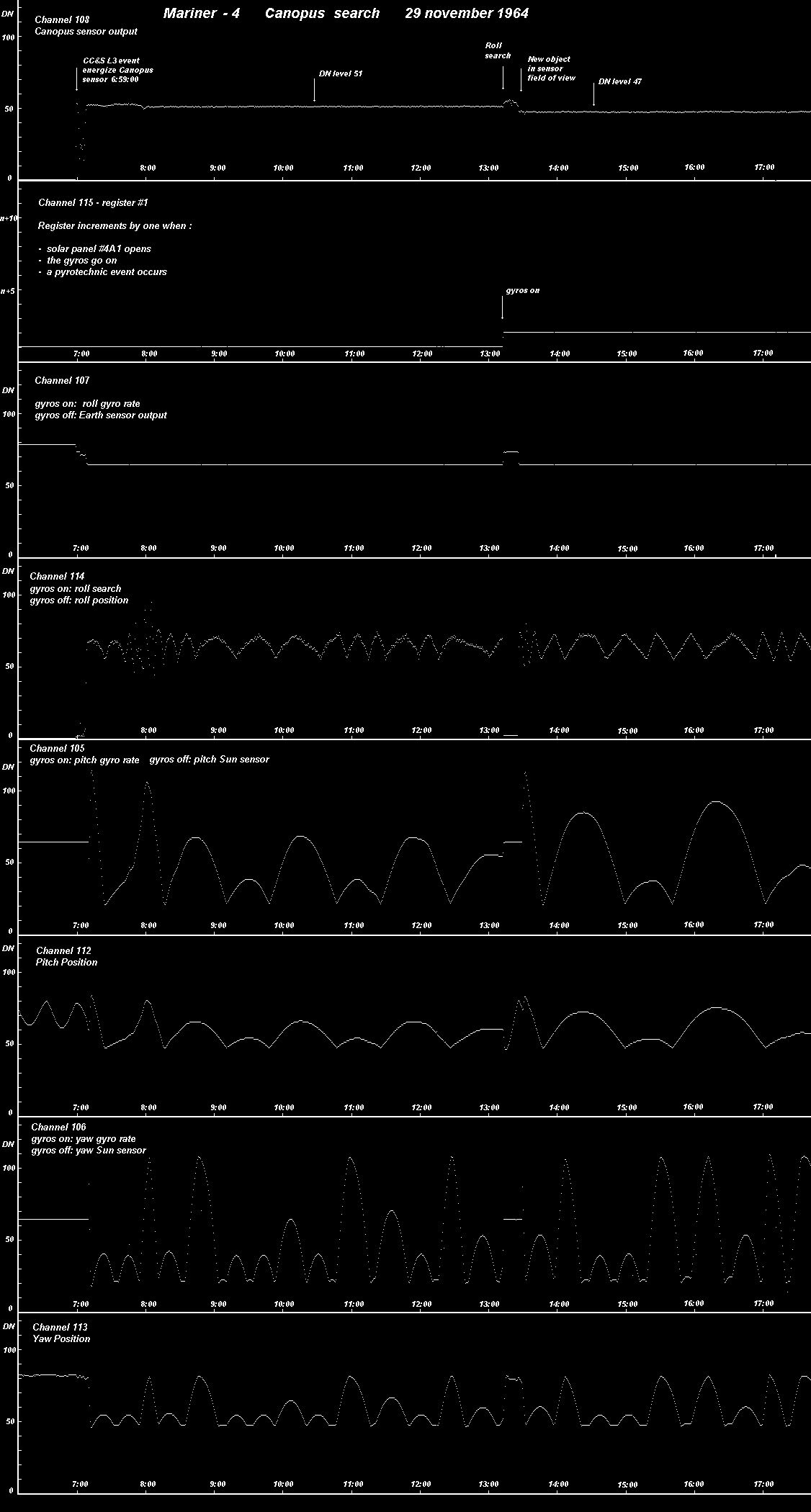
Engineering data Channels
| Channel | Measurement | Units | DN = 0 | DN = 60 | DN = 126 |
| 108 | Canopus sensor output | Volts | 0.0 | 1.41 | 2.95 |
| 107 | gyros on: roll gyro rate gyros off: Earth sensor output |
mr/sec millifootcandle |
+16.8 -27.8 |
+1.05 -2.63 |
-16.3 +41.4 |
| 114 | gyros on: roll search gyros off: roll position |
mr/sec mr |
- +26.2 |
- +1.65 |
- -25.4 |
| 105 | gyros on: pitch gyro roll rate gyros off: pitch Sun sensor |
mr/sec mr* |
+19.5 +16.1 |
+1.21 +0.66 |
-18.5 -14.8 |
| 112 | pitch position | mr* | 30 DN = +50 | 60 DN = +10 | 100 DN = -175 |
| 106 | gyros on: yaw gyro roll rate gyros off: yaw Sun sensor |
mr/sec mr* |
+20.1 +15.5 |
+1.25 +0.42 |
-19.5 -14.0 |
| 113 | yaw position | mr* | 30 DN = +60 | 60 DN = +10 | 100 DN = -175 |
Last Updated: 2002.07.01